

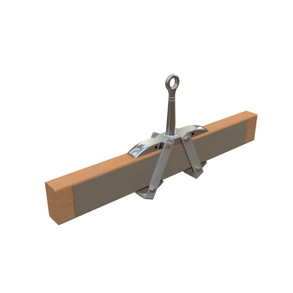


Truss-T-Grip® is a rope access and fall arrest anchor point designed for use on timber members such as trusses and rafters. It doesn’t rely on penetration of timber members by screws or any other means of their modification. Instead, it
utilises a unique clamping mechanism which compresses the timber rather than splitting it in the event of arresting a fall. It comes complete with 2 stainless steel truss armour plates. Waterproofing is achieved by Flexatile product sold separately.
Truss-T-Grip® is stocked in 3 most common truss/ rafter sizes:
TG9035 (fits trusses 90mm x 30mm), TG10050 and TG20050 but it can be made to suit any truss/ rafter size.
Special Features:
- Compression clamp mechanism
- Easy installation and removal
- Can be used as a temporary anchor
- Fits all standard truss and rafter sizes
Uses:
Designed for industrial rope access (abseiling) and to support a fall arrest load of 15 kN in any direction provided a suitable personal shock absorber is used. Installation by trained and certified personnel in accordance with AS/NZS AS/NZS 1891.4:2025, ISO 22846 (2020) and manufacturer’s instructions.
Material Used:
Investment cast grade 316 Stainless Steel
Finish:
Electro polish
Ultimate Load:
Rope access: 15 kN
Fall arrest: 15 kN
Dimensions:
- Height – 180 mm
- Eye Diameter – 22 mm
Weight:
- TG9035 – 2,725 g
- TG10050 – 3,160 g
- TG20050 – 3,175 g
Fixing Details:
Timber truss or rafter – min 90mm x 35mm
Things To Know:
Truss-T-Grip® anchor points have been designed for applications in both rope access (abseiling) and fall arrest. They will withstand loads of 15 kN in all directions when installed according to our instructions. Keep in mind that common size trusses and rafters on their own are not strong enough to withstand the lateral force of 15 kN and that’s why the structure must be reinforced as described below!
Truss-T-Grip anchor points are stocked in 3 most common rafter sizes but can be manufactured to accommodate any rafter size. They can be installed permanently or temporarily, depending on requirements. All types of Truss-T-Grip are supplied with Roof-tite flashing and Armour plates to provide for permanent installation.
Anchor Rating:
The Truss-T-Grip anchor system has been independently tested in accordance with AS/NZS 5532:2025 and verified as a 15 kN rated rope access/ fall arrest anchorage device.
- Timber truss/rafter size: 90mm x 35mm, 100mm x 50mm, 200mm x 50mm
- Loading: Truss-T-Grip anchor points can be loaded in all directions always in sheer with the roof.
Tools and Materials Needed:
Hammer, 2 ring spanners, drop saw or hand saw, grinder with diamond wheel, caulking gun, Stanley knife, Flexatile flashing, framing pine to reinforce roof structure (point 6), nail gun or a drill.
Installation Steps:
- Remove tiles to expose the rafter.
- Place Truss-T-Grip body on the rafter.
- Install the U-straps with friction plates to the underside of the rafter ensuring the Armour plates are held firmly against the rafter. The anchor body shape provides for attachment of two sizes of friction plates at two different spots. Ensure the correct pair of holes on the anchor body is used for fixing. They are 35mm or 50mm wide (this depends on the rafter size) and attach with M8 bolts (provided). You can choose to work from the inside the roof cavity or from the roof top. A team of two is ideal with one person inside and one outside.
- Use a hammer to knock the friction plates into compression and tighten the bolts.
- Install 2 small nails (provided) next to the friction plates to keep them engaged at all times.
- Extra nogging between the rafters cut to size must be used to strengthen the roof structure. A piece of pine the size of the rafter will do the job perfectly (shown in red). Use a nail gun or a drill to secure it in place with suitable fixings.
- Use angle grinder with a diamond wheel to make a small hole in the tile, positioned directly above the anchor eye. Ensure the hole will be in the correct position by partially replacing the tile and marking the position with a texter. Once the position has been determined cut the outline of a rectangular hole connecting the diagonally opposite corners of the hole with two cuts in the shape of letter X. Then tap the tile gently with a hammer creating a rectangular hole. Replace all tiles and close the hole in the roof.
- Apply Flexatile one piece flashing and tuck the excess length under the tiles at the top. The bottom can be cut off with a Stanley knife or folded under the roof tile.
- The installation is now complete
Annual Re-certification:
All anchor points must be inspected and certified before their initial use and subsequently on regular basis to satisfy the requirements set out in AS/NZS 1891.4:2025 and ISO 22846 (2020).
Note:
The roof structure must be assessed by a structural engineer unless it is clear to a suitably qualified person that it is capable of withstanding the forces imposed on it during arresting of a fall.
Disclaimer:
All product specifications and technical descriptions, recommendations and other information provided in this document are given as general guidance and advice, and are to be considered in conjunction with Safety Roof Anchors installation instructions and any other data available and applicable to each particular standard product or system. Use of such data is however the user’s sole responsibility taking into account the intended application and actual conditions existing on the specific worksite. Consequent selection of the right product for any particular use remains the user’s ultimate responsibility.
Safety Roof Anchors is thvrefore not obligated or liable for any direct or indirect, incidental or consequential damages, losses or expenses in connection with, or by reason of the suitability and use of or otherwise, any product or system for any purpose. Implied warranties of merchantability or fitness for any particular purpose are specifically excluded. Safety Roof Anchors maintains a policy of continuous improvement and development, and therefore reserves the right to modify, amend or otherwise alter product and system designs and specification, models and part numbers, colours and pricing etc., without prior notice. Safety Roof Anchors accepts no liability whatsoever for incorrect information, errors or omissions.
Maintenance:
Inspection required by competent person at intervals not exceeding 12 months as specified in 1891.4:2025, and ISO 22846 (2020).
Standards:
Complies with WHS Act 2011 and relevant Codes of Practice.
Australian Standard – AS/NZS 1891.4:2025, AS/NZS 5532:2025
ISO 22846 (2020)