


Special Features:
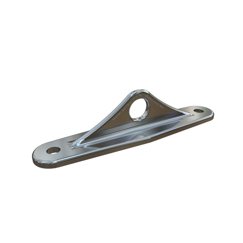
- 15 kN rated anchors device
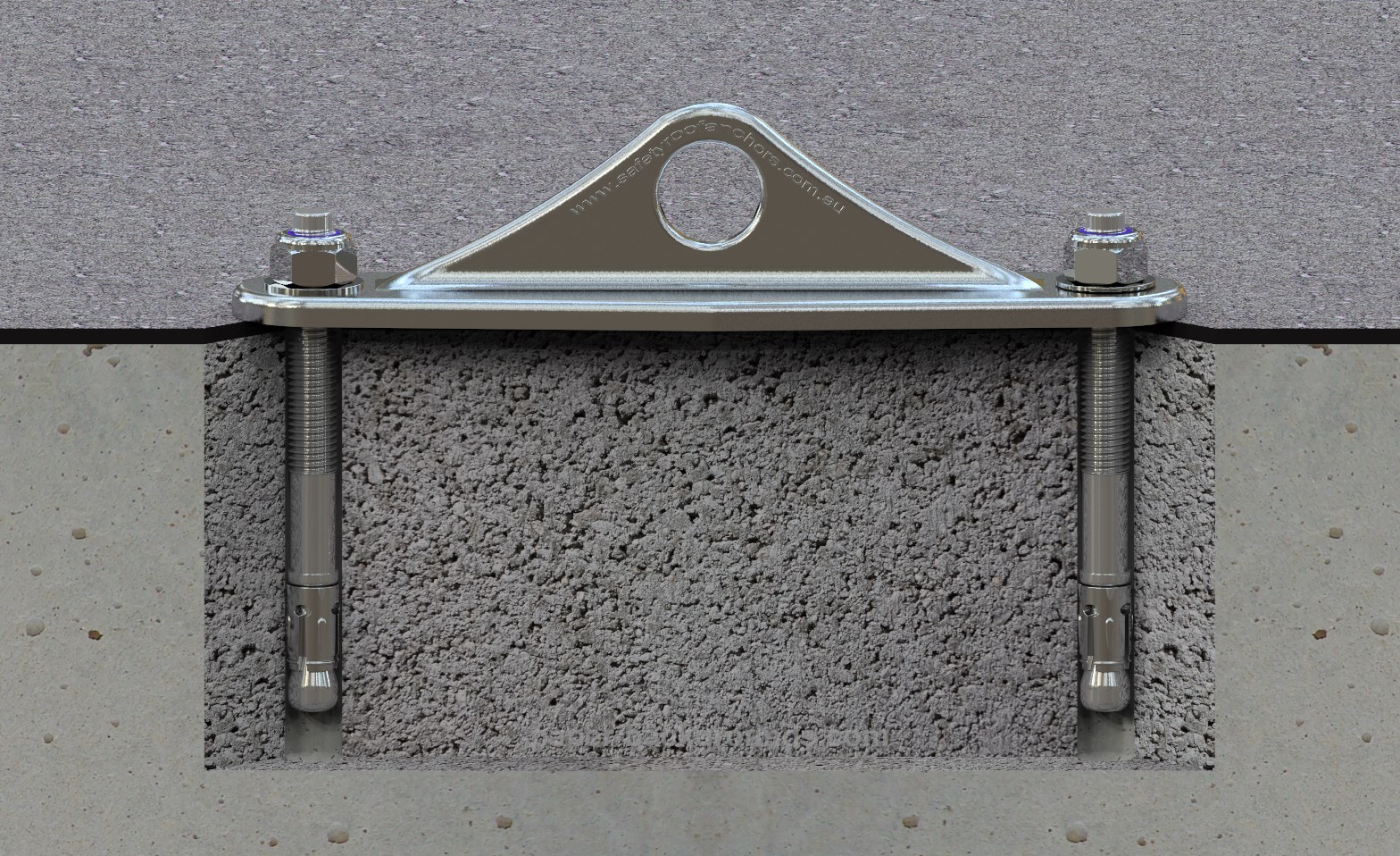
- Dual-fix design using two independent fixings
- Designed specifically for tensile loading applications
- Accommodates multi-directional loading
- Large 25 mm attachment eye
- Investment cast 316 stainless steel construction
- Electropolished finish
- Suitable for rope access and fall arrest applications
- Suitable for installation into concrete and steel
- Designed and manufactured for professional height safety applications
Material Used:
Investment Cast 316 Stainless Steel
Finish:
Electro polished
Abseil Capacity:
15 kN
Fall Arrest Capacity:
15 kN
Dimensions:
- Overall length – 240 mm
- Hole to hole centres – 200 mm
- Eye Diameter – 25 mm
- Weight – 710 g
Fixing Details:
Use only approved M12 mechanical or chemical anchors meeting the required performance criteria.
- Minimum embedment 100mm for wedge anchors
- Suitable for cracked and non-cracked concrete
- Minimum tensile resistance ≥ 18kN
- Minimum embedment 110mm for chemical anchors
Examples include:
- 2 x Chemical HILTI HVU M12 or injectable equivalent such as HILTI RE-500 HOLE 14 DIA)
- 2x SRA wedge anchor M12x125mm (HOLE 12 DIA)
- 2 x HSL 3 GR M12 (HOLE 18 DIA) or 2 HSL 3 GR M10 (HOLE 15 DIA)
- 2x Hilti HST3-R M12x125mm (HOLE 12 DIA)
- 2 x Through bolt M12 (HOLE 14 DIA)
Concrete specifications:
Min. concrete strength: 27.5 – 30 Mpa
Min slab thickness: 150 mm
Things To Know:
AA408 is designed for installation in concrete and steel. It has been specifically developed for tensile loading applications. It is suitable as a re-belay/ aid climbing anchor, tensile rope access anchor or fall arrest anchor. It should be used in place of collared eye bolts in all applications where they are loaded under an angle greater than 20° with the surface they are installed in.
Anchor Rating:
The AA408 dual-fix anchor system has been independently tested in accordance with AS/NZS 5532:2025 and verified as a 15 kN rated rope access/ fall arrest anchorage device.
Fixing Options:
Use only approved M12 mechanical or chemical anchors meeting the required performance criteria.
- Minimum embedment 95 mm for wedge anchors
- Suitable for cracked and non-cracked concrete
- Minimum tensile resistance ≥ 18kN
- Minimum embedment 110mm for chemical anchors
Examples Include:
- 2x Chemical HILTI HVU M12 or injectable equivalent such as HILTI RE-500 (HOLE 14 DIA)
- 2x SRA wedge anchor M12x125mm (HOLE 12 DIA)
- 2x HSL 3 GR M12 (HOLE 18 DIA) or 2x HSL 3 GR M10 (HOLE 15 DIA)
- 2x Hilti HST3-R M12x125mm (HOLE 12 DIA)
- 2x Through bolt M12 (HOLE 14 DIA)
Concrete Specifications:
Min. concrete strength: 25 Mpa
Min slab thickness: 150 mm
Min. distance to edge: 200 mm
Min. distance to another anchor: 200mm
Note:
Edge distances less than the stated minimum may be permitted where verified by anchor manufacturer design (e.g. Hilti). Verification must be based on project-specific parameters including concrete strength, embedment depth, anchor size, and edge condition, with documented capacity calculations.
Loading:
The anchor is designed to accommodate multi-directional loading typical of fall arrest and rope access systems including tension. Maximum strength is achieved when loading along the axis!
Tools Needed For Installation:
Rebar detector, Rotary hammer drill, Masonry drill bit 12, 14, 18 or 15 (HSL M10) air pump, cleaning brush and torque wrench.
Installation Steps – M12 HILTI HVU chemset in concrete:
- Use Hilti Reo Scan or similar device to avoid drilling the steel reinforcement in concrete.
- Mark the positions for holes to be drilled.
- Drill two Dia 14mm x 110mm holes. When you start drilling the second hole, double check your holes line up with the anchor holes. Ensure the holes are parallel and 90° with the drilled surface.
- Clean the holes 3 times with compressed air and cleaning brush.
- Insert one Hilti HVU M12 chemical pack in each hole.
- Using rotary hammer with appropriate setting tool, install 2 stainless steel M12 rods through the holes in the base of AA408 anchor. The rods must have sharp tips to allow for correct mixing of chemical.
- Allow sufficient drying time as per Hilti HVU instructions.
- Install one M12 washer and one M12 nylock nut on each rod ensuring minimum of 3 threads are showing when nuts are fully tightened.
Note:
The 3 threads are important for a secure attachment of a separate M12 eye nut which is needed to complete the proof load of individual rods/fixings upon installation.
When installing through water proofing membrane, a full gasket of a membrane compatible sealant is recommended between and around the anchor base plate and the membrane.
Installation Steps – M12x 125mm SRA wedge anchor fixings in concrete:
- Use Hilti Reo Scan or similar device to avoid drilling the steel reinforcement in concrete. Alternatively use SRA Reo-Buster if hitting steel is a problem.
- Mark the positions for holes to be drilled.
- Drill two DIA 12mm x 100mm holes through the anchor plate fixing holes. Ensure the holes are parallel and 90° with the drilled surface.
- Clean the holes with compressed air and cleaning brush.
- Assemble both SRA wedge anchors onto the anchor body and check they line up with the marked holes.
- Position the assembled unit over the drilled holes. Using an SDS setting tool or a hammer, alternately drive each wedge anchor until both washers are fully seated against the surface.
- Use a torque wrench to apply correct torque as per SRA wedge anchor instructions (50 Nm)
- Once a prescribed torque is achieved in both fixings, the installation is complete. Original hex nuts and washers will suffice or may be upgraded to M12 nylock nuts. As an alternative, a heavy-duty thread locker (Loctite Red 271) or s/s spring washers can be used with the original nuts. Ensure minimum of 3 threads are showing when nuts are fully tightened.
Note:
The 3 threads are important for a secure attachment of a separate M12 eye nut which is needed to complete a proof load of individual rods/fixings upon installation and annually.
Installation Steps – M12x125mm Hilti HST3-R:
- Use Hilti Reo Scan or similar device to avoid drilling the steel reinforcement in concrete.
- Mark the positions for holes to be drilled.
- Drill two DIA 12mm x 100mm holes through the anchor plate fixing holes. Ensure the holes are parallel and 90° with the drilled surface.
- Clean the holes with compressed air and cleaning brush.
- Assemble both Hilti HST3-R onto the anchor body and check they line up with the marked holes.
- Position the assembled unit over the drilled holes. Using an SDS setting tool or a hammer, alternately drive each wedge anchor until both washers are fully seated against the surface.
- Use a torque wrench to apply correct torque as per Hilti M12x125mm HST3-R instructions.
- Once a prescribed torque is achieved in both fixings, the installation is complete. Original hex nuts and washers will suffice or may be upgraded to M12 nylock nuts. As an alternative, a heavy-duty thread locker (Loctite Red 271) or s/s spring washers can be used with the original nuts. Ensure minimum of 3 threads are showing when nuts are fully tightened.
Note:
The 3 threads are important for a secure attachment of a separate M12 eye nut which is needed to complete the proof load of individual rods/fixings upon installation.
Installation Steps – M12 Hilti HSL 3 GR:
- Use Hilti Reo Scan or similar device to avoid drilling the steel reinforcement in concrete.
- Mark the positions for holes to be drilled.
- Assemble both HSL’s onto the anchor body and check they line up with the marked holes.
- Drill two DIA 18mm x 125mm holes. When you start drilling the second hole, double check the holes line up with the HSL’s in your assembly. Ensure the holes are parallel and 90° with the drilled surface.
- Clean the holes with compressed air and cleaning brush.
- Offer the whole assembly to the drilled holes and tap both HSL’s repeatedly with hammer until fully in.
- Use a spanner to apply correct torque as per Hilti HSL-3B instructions.
- Once a prescribed torque is achieved in both fixings, the installation is complete. In the overhead applications, the original hex nuts and washers will suffice or may be upgraded to M12 nylock nuts. As an alternative, a heavy-duty thread locker (Loctite Red 271) or s/s spring washers can be used with the original nuts. Ensure minimum of 5 threads are showing when nuts are fully tightened.
Note:
The 3 threads are important for a secure attachment of a separate M12 eye nut which is needed to complete the proof load of individual rods/fixings upon installation.
Installation Steps – M12 through bolt:
- Use Hilti Reo Scan or similar device to avoid drilling the steel reinforcement in concrete.
- Mark the positions for holes to be drilled.
- Drill two DIA 14 holes. When you start drilling the second hole, double check your holes line up with the anchor holes. Ensure the holes are parallel and 90° with the drilled surface.
- Insert two M12 stainless steel rods cut to size. Add two backing plates (BP2 or BP3) to each rod on the back side and M12 washer to each rod on the front side.
- Install four M12 lock nuts; one for each end of the rod and tighten to 40 Nm using two spanners. Ensure minimum of 3 threads are showing when nuts are fully tightened.
Proof load and certification:
All chemical and friction anchorages must be proof loaded before their initial use and subsequently on regular basis unless detailed records of fixings method are available to satisfy the requirements set out in AS/NZS 1891.4:2025 and ISO 22846:2020.
- Upon installation proof load each rod (fixing) individually to 7.5 kN
- Do not proof load the bracket because this can mask issues during the test. Proof loading each rod individually is the best practice! If for any reason the fixings can’t be proof loaded individually, proof load the bracket to 7.5kN.
Through bolts must be visually inspected – do not proof load!
Note:
The structure must be assessed by a structural engineer unless it is clear to a suitably qualified person that it can withstand the forces imposed on it during arresting of a fall and during work positioning.
Disclaimer:
All product specifications and technical descriptions, recommendations and other information provided in this document are given as general guidance and advice and are to be considered in conjunction with Safety Roof Anchors installation instructions and any other data available and applicable to each particular standard product or system. Use of such data is however the user’s sole responsibility taking into account the intended application and actual conditions existing on the specific worksite. Consequent selection of the right product for any particular use remains the user’s ultimate responsibility.
Safety Roof Anchors is therefore not obligated or liable for any direct or indirect, incidental, or consequential damages, losses or expenses in connection with, or by reason of the suitability and use of or otherwise, any product or system for any purpose. Implied warranties of merchantability or fitness for any particular purpose are specifically excluded. Safety Roof Anchors maintains a policy of continuous improvement and development, and therefore reserves the right to modify, amend or otherwise alter product and system designs and specification, models and part numbers, colours and pricing etc., without prior notice. Safety Roof Anchors accepts no liability whatsoever for incorrect information, errors or omissions.
Maintenance:
Anchors must be inspected by a competent person at intervals not exceeding 12 months.
Inspection should include:
- visual inspection of anchor condition
- verification of fixing integrity
- load testing where required
Inspection procedures should follow relevant Australian Standards.
Standards:
Complies with WHS Act 2011 and relevant Codes of Practice.
- AS/NZS 5532:2025 – Manufacturing requirements for single-point anchors
- AS/NZS 1891:2025 – Fall arrest systems and devices
- ISO 22846:2020 – Rope access systems